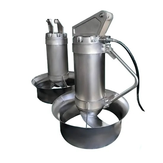
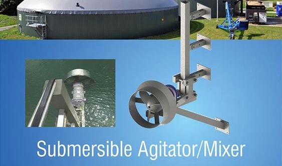
Submersible Mixers Description
From an engineering perspective, submersible mixers are robust, integrated pump-motor units where the impeller is an extension of the motor shaft, all housed in a single, sealed unit. This hermetic design isolates all moving parts from the process fluid, making them ideal for abrasive or corrosive media. They are characterized by their specific hydraulic output (flow rate vs. head generated), which defines their mixing intensity, and are engineered to handle fluids with viscosities ranging from water-like to several thousand centipoise.
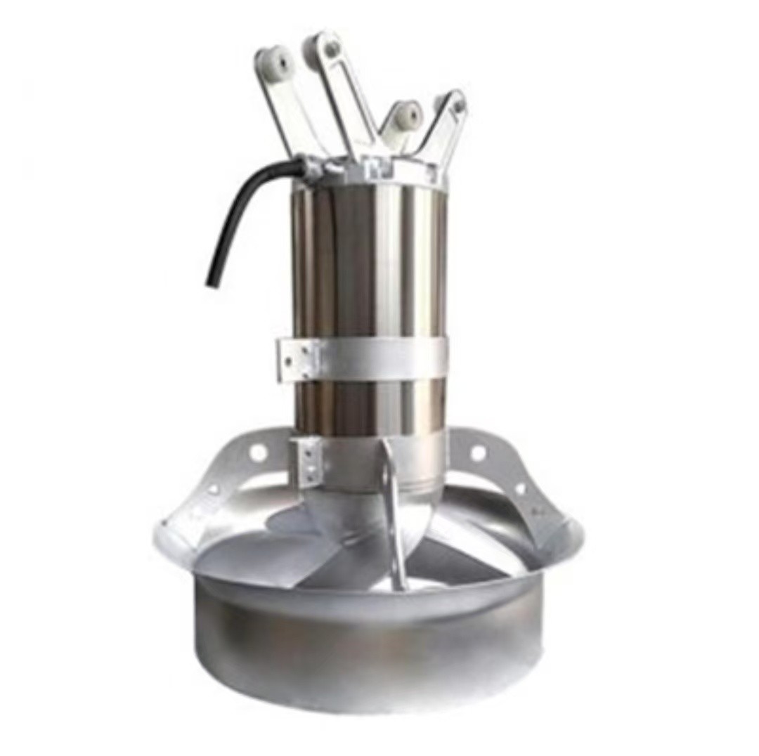
Submersible Mixers principle
Component
The fundamental principle is momentum transfer. The rotating impeller imparts kinetic energy to the surrounding fluid, creating a high-velocity jet. This jet entrains surrounding stationary fluid, creating a bulk flow that circulates throughout the entire tank volume. The design aims to minimize energy losses from turbulence at the impeller tip and instead convert maximum power into laminar, directional flow to achieve complete tank turnover with minimal power input.
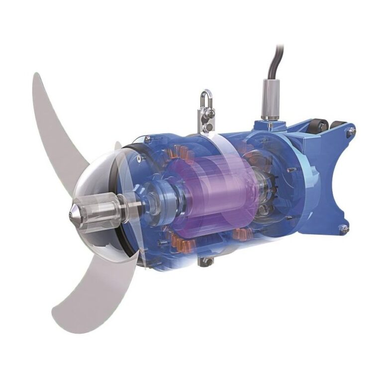
| Componente | Material |
|---|---|
| Shell | Stainless steel/GG25 cast iron |
| Impeller | Stainless steel/Fiberglass Polyurethane |
| Shaft | ASTM431 or 420 stainless steel |
| Mechanical seal | Corrosion resistant cemented tungsten carbide/or silicon carbide |
| Guide rod | ASTM304 Stainless steel |
| Lifting bracket | ASTM304 Stainless steel |
| Lifting cable | ASTM304 Stainless steel |
| Fasteners | ASTM321 Stainless steel |

Submersible Mixers Parameter
| Model | Power (kW) | Current (A) | Rotary speed (rpm) | Impeller diameter (mm) | Force (N) | Weight (kg) |
|---|---|---|---|---|---|---|
| SMB0.85/8-260/3-740/C/S | 0.85 | 3.4 | 740 | 260 | 163 | 55/58 |
| SMB1.5/6-260/3-980/C/S | 1.5 | 4.4 | 980 | 260 | 290 | 55/58 |
| SMB2.2/8-320/3-740/C/S | 2.2 | 5.9 | 740 | 320 | 582 | 74/77 |
| SMB4/6-320/3-980/C/S | 4 | 10.8 | 980 | 320 | 609 | 74/77 |
| SMB1.5/8-400/3-740/S | 1.5 | 5.6 | 740 | 400 | 382 | 76/80 |
| SMB2.5/8-400/3-740/S | 2.5 | 7.3 | 740 | 400 | 575 | 76/80 |
| SMB3/8-400/3-740/S | 3 | 8.6 | 740 | 400 | 642 | 78/82 |
| SMB4/6-400/3-980/S | 4 | 10.3 | 980 | 400 | 1010 | 80/84 |
| SMB4/12-620/3-480/S | 4 | 14 | 480 | 620 | 1230 | 240/245 |
| SMB5/12-620/3-480/S | 5 | 18.2 | 480 | 620 | 1420 | 240/245 |
| SMB7.5/12-620/3-480/S | 7.5 | 28 | 480 | 620 | 1963 | 255/270 |
| SMB10/12-620/3-480/S | 10 | 32 | 480 | 620 | 2361 | 255/270 |
Energy-saving Submersible Mixers Selection
Energy Efficiency Drivers
Efficiency is driven by:
Selection Engineering
Engineers select based on Reynolds Number for the application (laminar vs. turbulent mixing), Power Number (Np) of the impeller, and required Turnover Time. The key equation is P = Np * ρ * N³ * D⁵, where P is power, ρ is density, N is rotational speed, and D is impeller diameter. Selection involves solving for the optimal D and N that deliver the necessary flow (Q) within the power constraint, often using proprietary selection software provided by manufacturers.
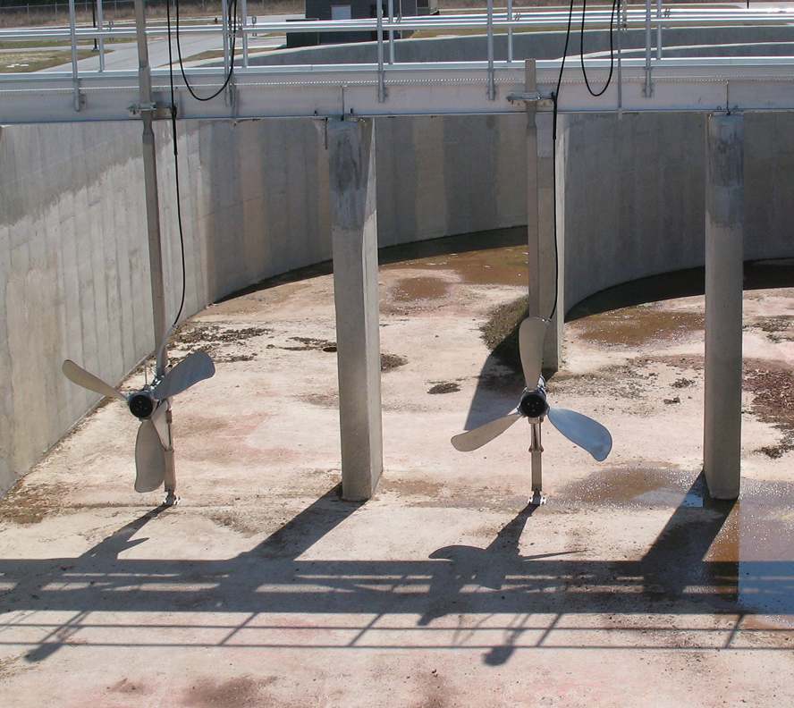
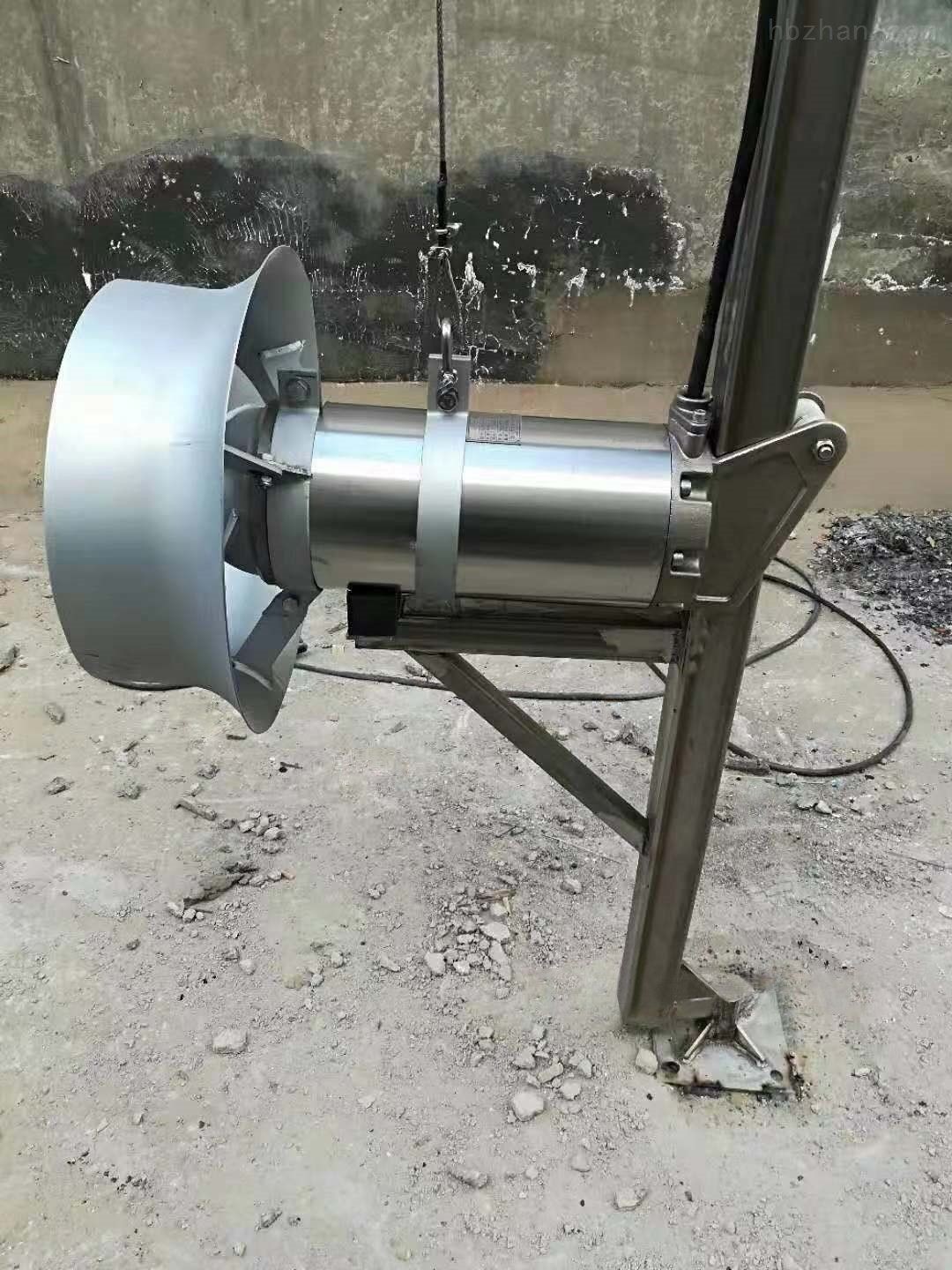
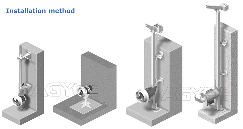
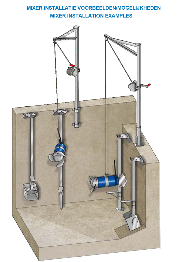
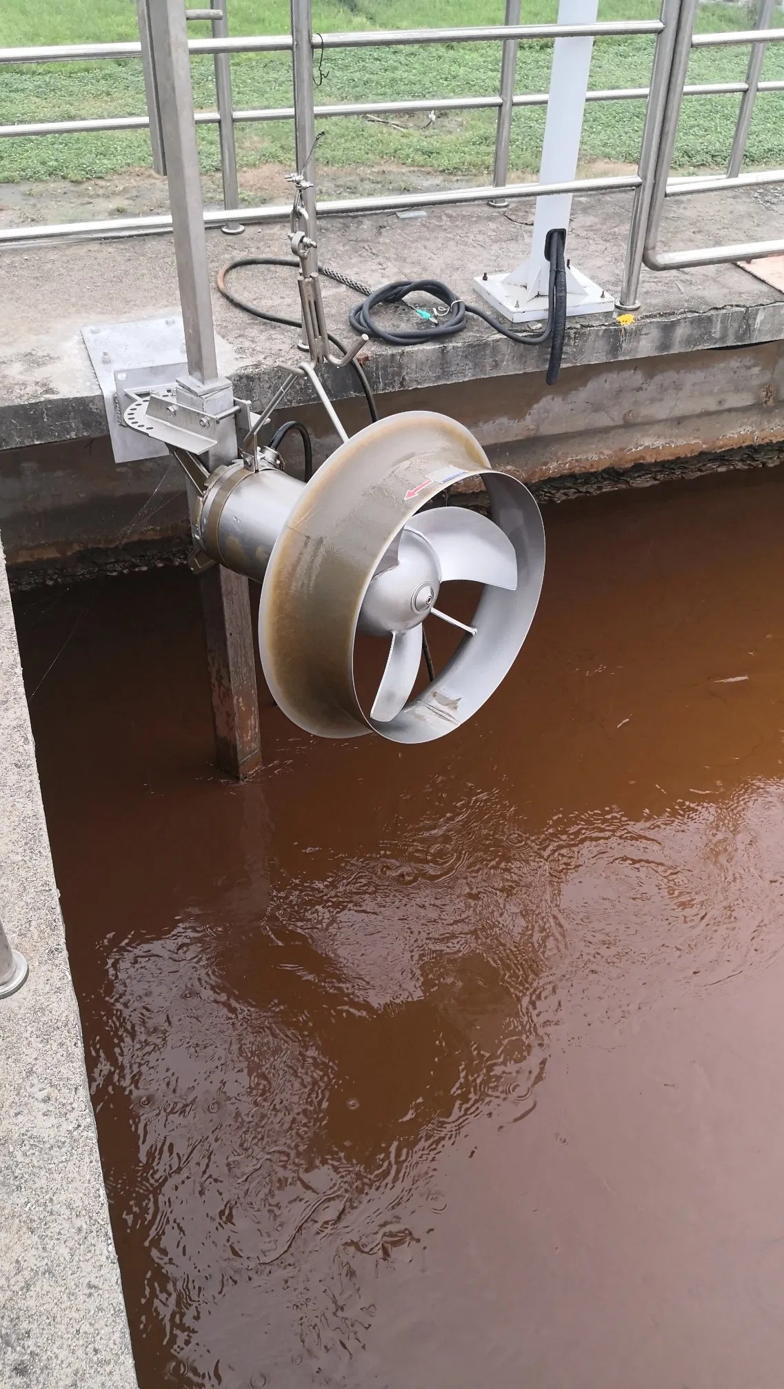
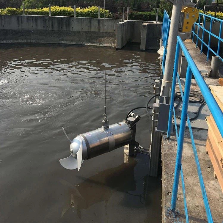
Submersible Mixers Installation Method

Installation is critical for performance.
Engineering drawings must specify:
Submersible Mixers Factor
Dominant factors are:
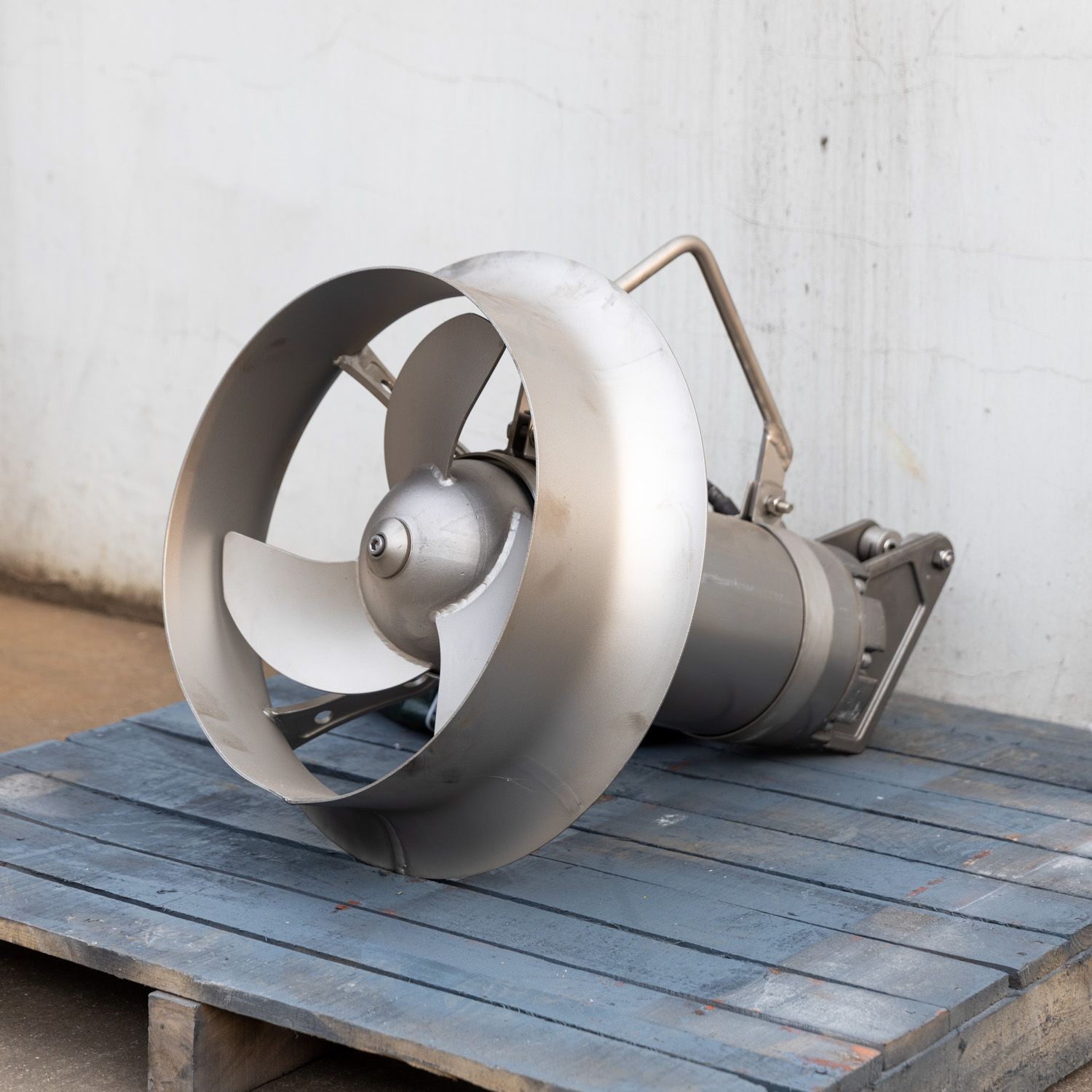
Submersible Mixers Features

Submersible Mixers Application
Supplier Information
We are a professional supplier specializing in high-efficiency Submersible Mixers, offering customized engineering solutions, bench-scale testing services, and robust equipment designed for demanding industrial and municipal applications.
Contact us today for a free application review and mixer selection recommendation!