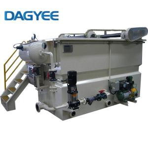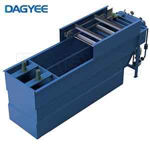
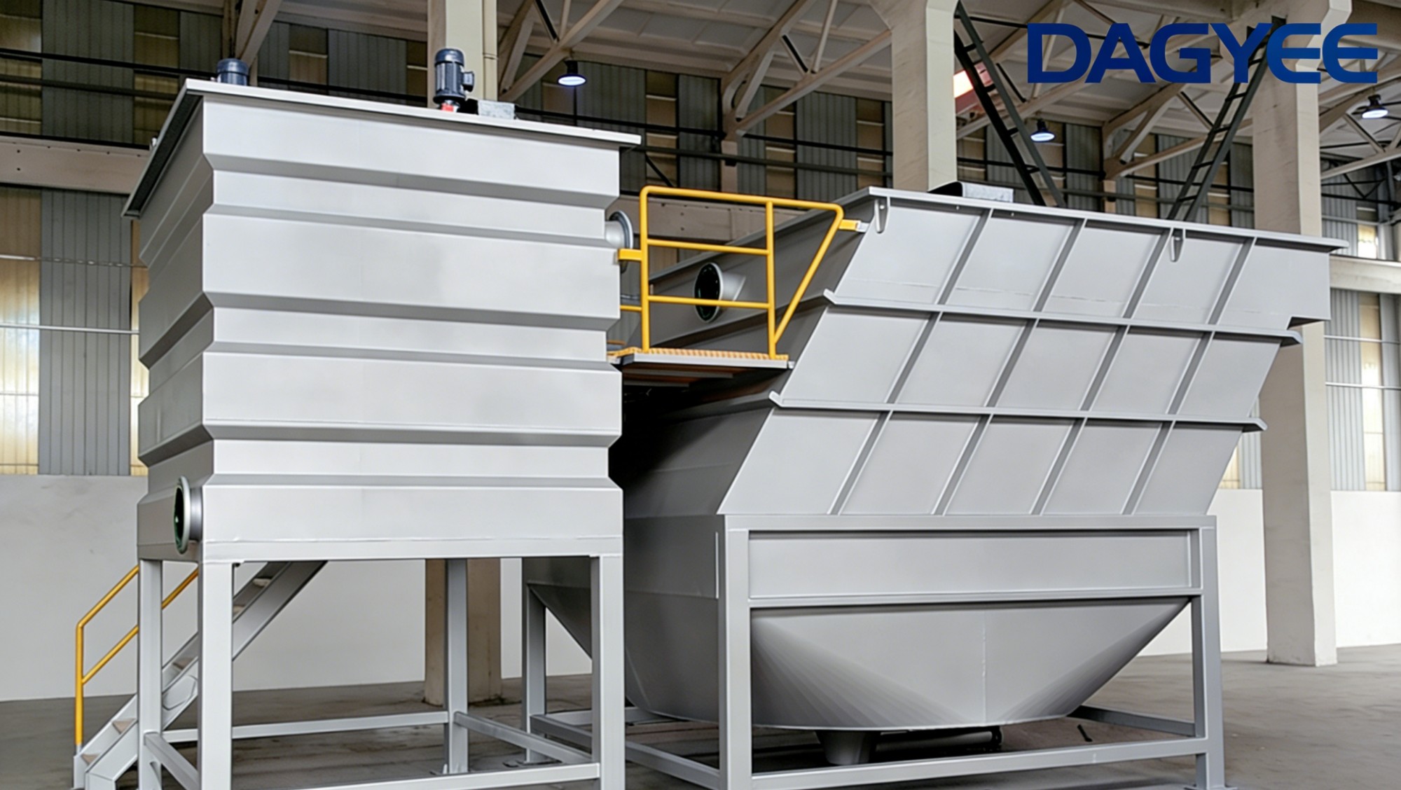
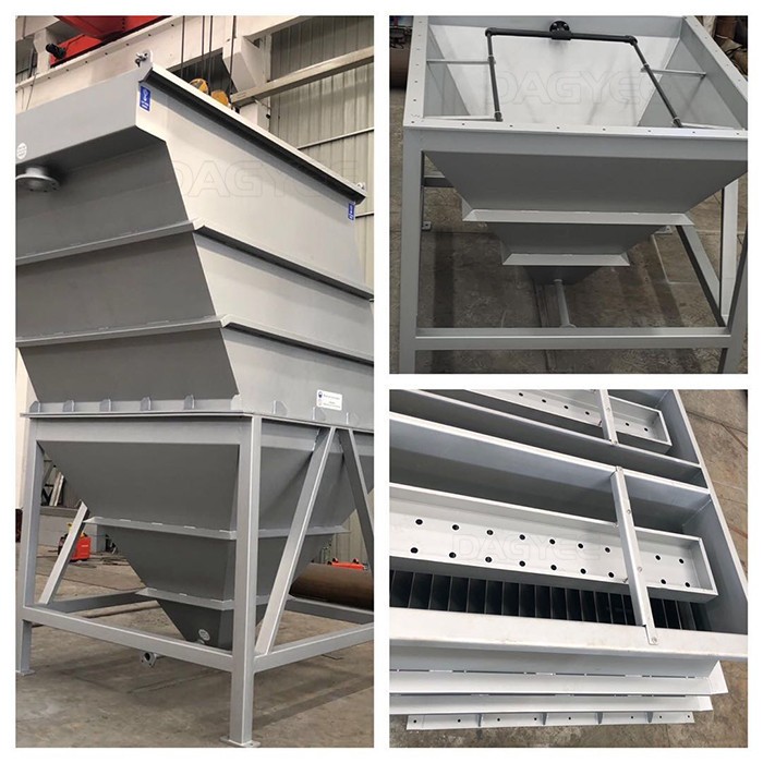
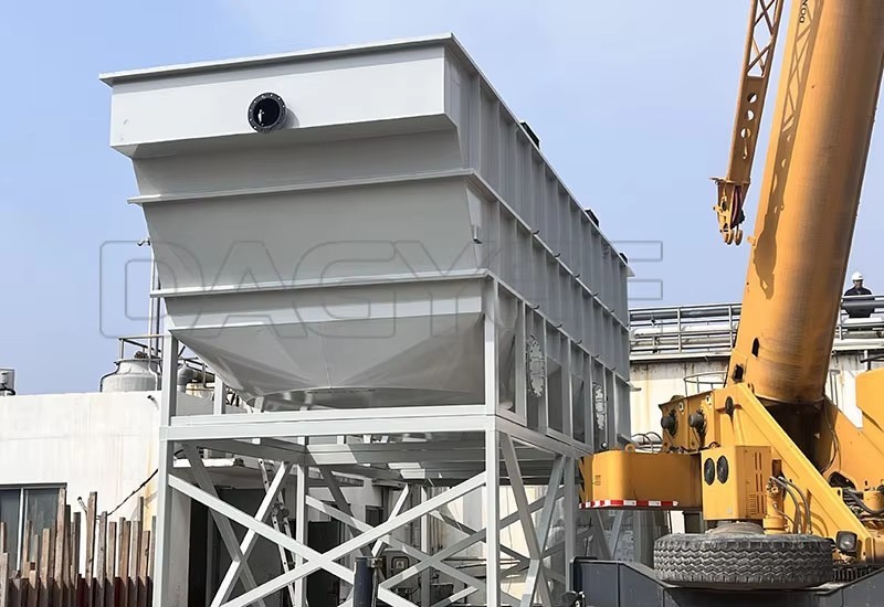
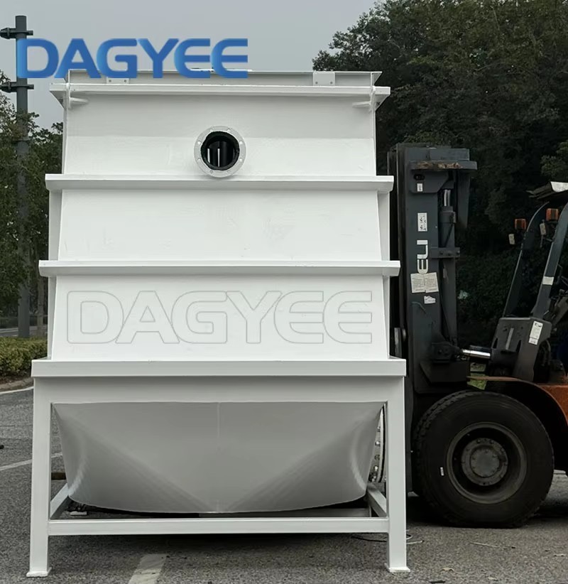
lamella clarifier for Chemical & Petrochemical Wastewater – Heavy-Duty Solids Removal for Industrial Effluents
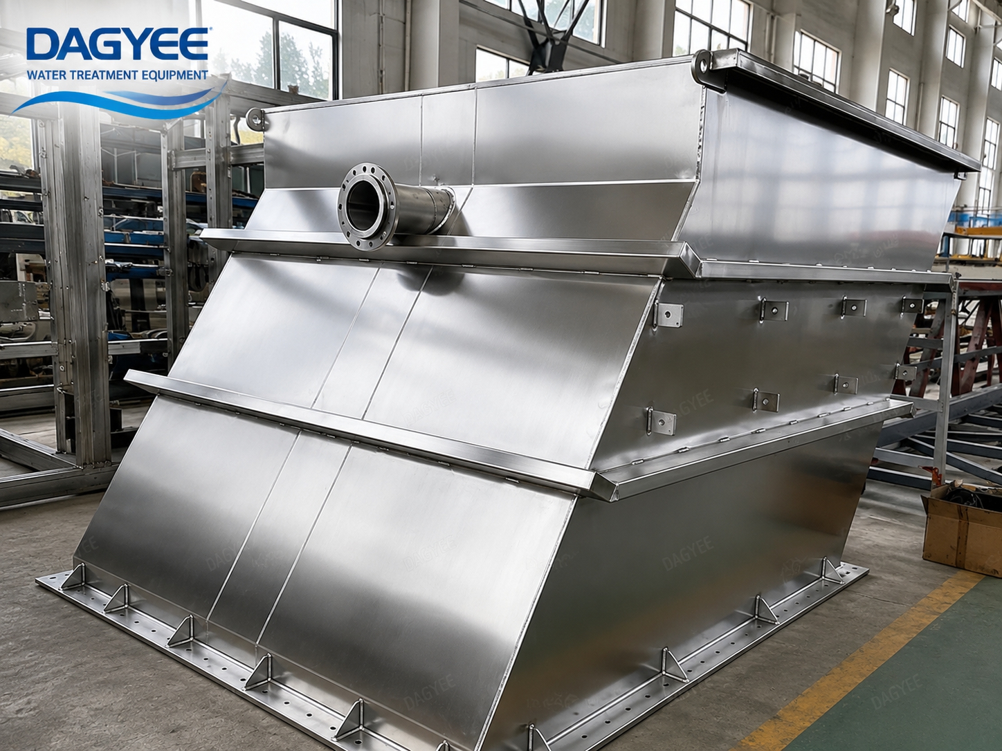
Chemical and petrochemical wastewater presents unique challenges for treatment. The streams can be highly variable in composition, pH, temperature, and contaminant load. Suspended solids may include catalysts, precipitated metals, chemical precipitates, and organic by-products. The water chemistry can be aggressive, requiring corrosion-resistant materials. Treatment systems must be robust, reliable, and capable of handling the demanding conditions of chemical processing.
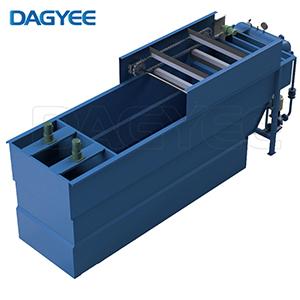
The DAGYEE Lamella Clarifier for Chemical & Petrochemical Wastewater is specifically engineered for these challenging applications. It provides high-efficiency solids removal from aggressive chemical streams, with construction materials selected for resistance to the specific wastewater chemistry. Whether you are treating refinery effluent, chemical plant wastewater, or process water from petrochemical production, this clarifier delivers consistent performance.
The system is designed to handle varying flow rates and solids loading while producing clarified water that meets discharge standards or is suitable for reuse. Its compact design saves valuable plant space, and its simple, reliable operation minimizes maintenance requirements.
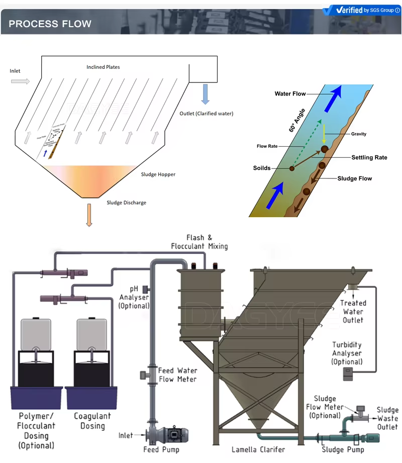
The lamella clarifier uses the same basic principle of inclined plate sedimentation, but with specialized features for chemical applications.
The Process Flow
Step 1: Feed Conditioning
Chemical wastewater enters the system, often after pH adjustment, coagulation, and flocculation. Chemical dosing may be provided to optimize solids removal.
Step 2: Chemical Addition (If Required)
For applications requiring chemical precipitation of metals or other dissolved contaminants, chemical reagents are added to form precipitates that can be settled.
Step 3: Lamella Clarification
The conditioned water flows upward through the inclined plate pack. The high effective settling area captures solid precipitates, catalyst fines, and other suspended particles. The clarified water overflows from the top of the unit.
Step 4: Solids Collection and Discharge
Settled solids slide down the plates to the sludge hopper. The concentrated sludge is discharged through a valve or pump system for further processing or disposal.
Step 5: Clear Effluent
The clarified water is discharged to the next treatment stage or to outfall, meeting permit requirements.
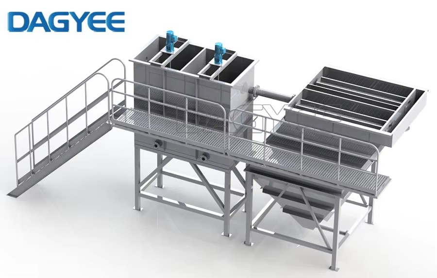
| Model | Capacities (m³/h) | Piping Connections (mm) | Physical Dimensions (m) | |||||
|---|---|---|---|---|---|---|---|---|
| Inlet | Effluent | Sludge | Backwash | L | W | H | ||
| DCL-005 | 5 | 80 | 80 | 50 | 50 | 2.55 | 1.60 | 2.90 |
| DCL-010 | 10 | 100 | 100 | 50 | 50 | 3.35 | 1.82 | 3.00 |
| DCL-015 | 15 | 100 | 100 | 50 | 50 | 3.35 | 2.02 | 3.00 |
| DCL-020 | 20 | 100 | 100 | 50 | 50 | 3.35 | 2.02 | 3.00 |
| DCL-030 | 30 | 150 | 150 | 50 | 50 | 4.20 | 2.22 | 3.00 |
| DCL-040 | 40 | 150 | 150 | 50 | 50 | 4.00 | 2.80 | 3.00 |
| DCL-050 | 50 | 200 | 200 | 50 | 50 | 4.65 | 2.82 | 3.00 |
| DCL-060 | 60 | 200 | 200 | 50 | 50 | 4.70 | 3.00 | 3.00 |
| DCL-070 | 70 | 250 | 250 | 50 | 50 | 6.40 | 2.60 | 3.00 |
| DCL-080 | 80 | 250 | 250 | 50 | 50 | 6.80 | 2.82 | 3.00 |
| DCL-100 | 100 | 250 | 250 | 50 | 50 | 7.05 | 3.02 | 3.00 |
| Feature | Benefit |
|---|---|
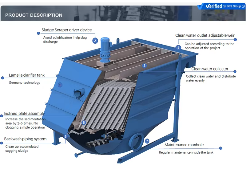
| Inclined Plate Arrangement | Settling area many times larger than floor space |
| Optimized Plate Angle | Self-cleaning design—solids slide down by gravity |
| Counter-Current Flow | Enhanced settling efficiency, denser sludge |
| No Moving Parts | Minimal mechanical failure, low maintenance |
| Modular Plate Pack | Easy installation, flexible design |
| Durable Materials | Stainless steel, HDPE, or engineered plastics |
| Integrated Flow Distribution | Even flow distribution across plates |
| Sludge Hopper Collection | Efficient sludge thickening and removal |
| Contaminant | Removal Efficiency | Notes |
|---|---|---|
| Suspended solids | High | Particles effectively removed |
| Turbidity | To very low levels | Typical clarified water quality |
| Free oils and greases | High | Under standard operating conditions |
| Emulsified oils | Moderate | Without chemical addition |
| Metal hydroxides | High | With proper flocculation |
| Colloidal particles | Moderate to high | With coagulant/flocculant addition |
| Settleable solids | High | Particles with density greater than water |
Municipal Wastewater Treatment: Primary and secondary clarification
Industrial Wastewater: Food processing, beverage, pulp & paper, chemical industries
Water Treatment Plants: Raw water clarification for drinking water production
Stormwater Treatment: Removal of suspended solids from stormwater runoff
Process Water Recycling: Clarification for water reuse systems
Mining Operations: Tailings clarification and process water recovery
Power Plants: Cooling water treatment and blowdown clarification
Aquaculture Systems: Water quality maintenance in recirculating systems
Customization Options
Plate Materials: Choice of stainless steel, polypropylene, PVC, or FRP based on chemical compatibility
Plate Coatings: Special coatings for specific applications (anti-fouling, anti-static, etc.)
Inlet Arrangements: Center feed, peripheral feed, or bottom feed configurations
Sludge Removal Systems: Chain-and-flight scrapers, traveling bridges, or suction systems
Instrumentation Packages: Level sensors, turbidity meters, sludge density monitors
Control Systems: Manual, semi-automatic, or fully automated PLC control
Accessories: Chemical dosing systems, flocculation aids, sampling points
Special Designs: Circular, rectangular, or square configurations based on space constraints
Installation Options
Full-Flow Installation
The clarifier is installed in the main cooling water return line, treating the entire flow before the water enters the cooling tower or heat exchangers.
Side-Stream Installation
A portion of the circulating cooling water is diverted through the clarifier and returned. This is a cost-effective approach for maintaining overall system cleanliness without treating the entire flow.
Make-Up Water Treatment
The clarifier is installed on the make-up water line to remove suspended solids before they enter the cooling system.
Pre-Filter Installation
The clarifier is installed ahead of heat exchangers or condensers to provide immediate protection against particulate fouling.
Why Choose DAGYEE Lamella Clarifiers
Proven Design: Hundreds of successful installations worldwide
Quality Materials: Only premium materials with proper certifications
Engineering Support: Custom design for specific wastewater characteristics
Performance Guarantee: Written performance guarantees based on design parameters
Comprehensive Service: From design to installation, commissioning, and after-sales support
Cost-Effective Solutions: Competitive pricing without compromising quality
Technical Innovation: Continuous improvement based on operational feedback
Global Experience: Applications across diverse industries and regions
Supplier Information
The DAGYEE Lamella Clarifier for Chemical & Petrochemical Wastewater provides heavy-duty, corrosion-resistant solids removal for the most demanding industrial applications. Designed for aggressive chemical streams, it delivers reliable performance with minimal maintenance.
Contact our team for a free consultation and customized system design for your chemical wastewater application.