
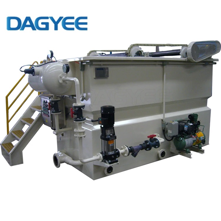
What Is DAF Dissolved air flotation
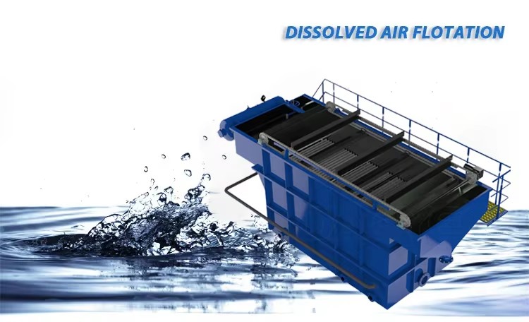
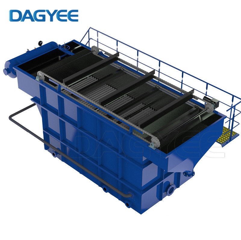
Dissolved Air Flotation (DAF) is an advanced water clarification process that removes suspended solids, oils, grease, and other contaminants from water and wastewater. The technology operates by dissolving air into water under pressure, then releasing it at atmospheric pressure in a flotation tank. This pressure release generates millions of microscopic air bubbles that attach to suspended particles, creating bubble-particle aggregates with lower density than water, causing them to rise rapidly to the surface for removal.
The DAF principle is based on fundamental physics: particles with density lower than water float, while those with higher density sink. By attaching micro-bubbles to suspended particles, we effectively reduce their overall density, transforming non-floatable particles into floatable ones. This process is governed by Stokes' Law, where bubble size, particle characteristics, and attachment efficiency determine separation performance. The microbubbles generated in DAF systems are typically 30-50 microns in diameter, providing optimal surface area for particle attachment without causing turbulence that would break apart flocculated particles.
Dissolved air flotation technical sheet

| DAF Model | Qm3/h | Piping Connections | Physical Dimensions(m) | Weight (Kg) | Operating Weight (Kg) |
|---|---|---|---|---|---|
| DAF-003 | 3 |
Inlet: DN50 Outlet: DN50 Sludge: DN100 Vent: DN100 |
L/L1: 3.7/2.8 W/W1: 2.4/1.16 H/H1: 2.2/1.7 |
1500 | 5000 |
| DAF-005 | 5 |
Inlet: DN80 Outlet: DN80 Sludge: DN100 Vent: DN80 |
L/L1: 4/3 W/W1: 2.4/1.16 H/H1: 2.2/1.7 |
1600 | 7000 |
| DAF-010 | 10 |
Inlet: DN100 Outlet: DN100 Sludge: DN100 Vent: DN100 |
L/L1: 4.65/3.8 W/W1: 2.7/1.36 H/H1: 2.4/1.9 |
2000 | 12000 |
| DAF-015 | 15 |
Inlet: DN125 Outlet: DN100 Sludge: DN150 Vent: DN100 |
L/L1: 5.6/4.5 W/W1: 2.9/1.66 H/H1: 2.5/2 |
2200 | 18000 |
| DAF-020 | 20 |
Inlet: DN150 Outlet: DN150 Sludge: DN150 Vent: DN100 |
L/L1: 5.9/4.8 W/W1: 3.2/1.96 H/H1: 2.5/2 |
3000 | 22000 |
| DAF-030 | 30 |
Inlet: DN150 Outlet: DN150 Sludge: DN150 Vent: DN100 |
L/L1: 6.8/5.5 W/W1: 3.2/2.16 H/H1: 2.7/2.2 |
3800 | 32000 |
| DAF-040 | 40 |
Inlet: DN200 Outlet: DN150 Sludge: DN150 Vent: DN100 |
L/L1: 8/6.7 W/W1: 3.6/2.6 H/H1: 2.7/2.2 |
5000 | 45000 |
| DAF-050 | 50 |
Inlet: DN200 Outlet: DN150 Sludge: DN150 Vent: DN100 |
L/L1: 8.4/7 W/W1: 3.6/2.6 H/H1: 2.7/2.2 |
5500 | 55000 |
| DAF-060 | 60 |
Inlet: DN250 Outlet: DN200 Sludge: DN150 Vent: DN100 |
L/L1: 9.9/8.4 W/W1: 3.8/2.8 H/H1: 2.9/2.4 |
6000 | 66000 |
| DAF-070 | 70 |
Inlet: DN250 Outlet: DN200 Sludge: DN150 Vent: DN100 |
L/L1: 10.4/9 W/W1: 3.8/2.8 H/H1: 2.9/2.4 |
6500 | 75000 |
| DAF-080 | 80 |
Inlet: DN250 Outlet: DN250 Sludge: DN150 Vent: DN100 |
L/L1: 10.8/9.4 W/W1: 4/3 H/H1: 2.9/2.4 |
7500 | 100000 |
| DAF-100 | 100 |
Inlet: DN300 Outlet: DN250 Sludge: DN150 Vent: DN100 |
L/L1: 12.1/10.6 W/W1: 4.2/3.2 H/H1: 2.9/2.4 |
9000 | 110000 |
| DAF-120 | 120 |
Inlet: DN300 Outlet: DN250 Sludge: DN150 Vent: DN100 |
L/L1: 12.5/11.4 W/W1: 4.4/3.4 H/H1: 2.9/2.4 |
10000 | 130000 |
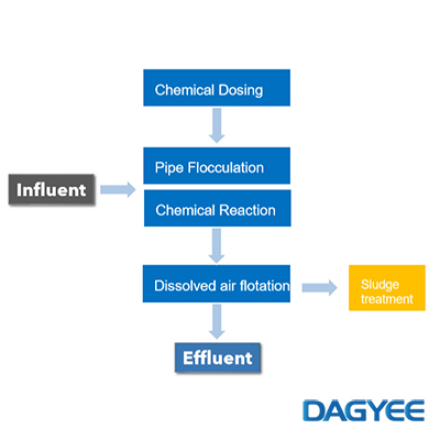
Dissolved air flotation process flow

Complete DAF Process Flow Diagram
The DAF process follows a carefully engineered sequence of operations:
1. Coagulation & Flocculation (Pre-treatment)
Raw water first enters the coagulation tank where chemical coagulants (alum, ferric chloride, or polyaluminum chloride) are added to destabilize suspended particles. The water then flows into the flocculation tank where gentle mixing promotes the formation of larger, settleable flocs. This pre-treatment stage is critical for optimal DAF performance, as properly formed flocs provide ideal surfaces for bubble attachment.
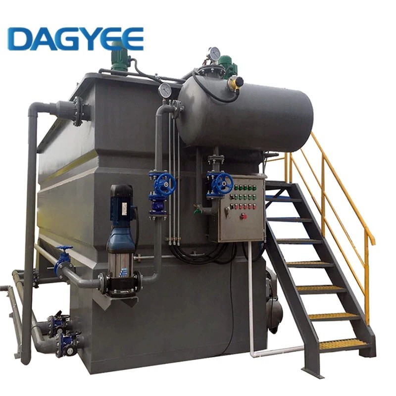
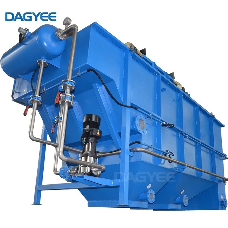
2. Pressurization & Air Dissolution
A side stream (typically 10-50% of the total flow) is pumped into the air saturation vessel. Compressed air is introduced at pressures between 4-6 bar, forcing air into solution according to Henry's Law. The saturation vessel is designed with specialized internals to maximize air-water contact time and achieve near-complete dissolution.
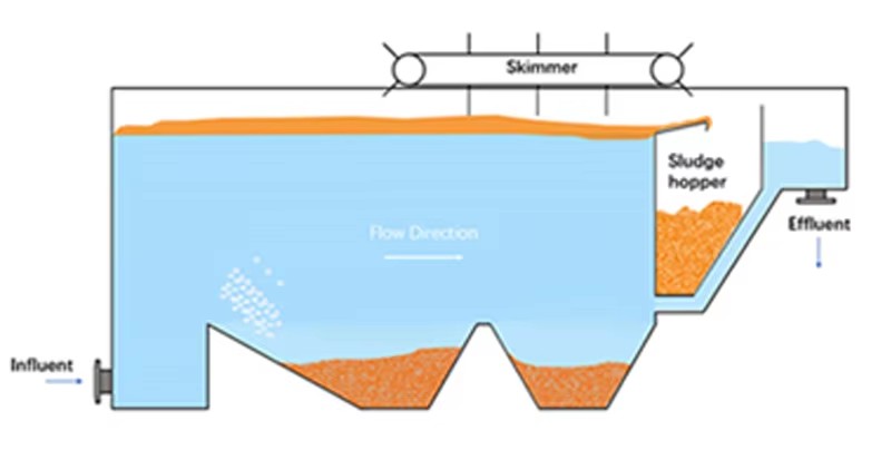
3. Pressure Release & Microbubble Formation
The supersaturated water is conveyed to the flotation tank inlet, where it passes through specially designed release nozzles or valves. The sudden pressure drop causes the dissolved air to come out of solution, forming billions of microscopic bubbles (30-50μm) that immediately interact with incoming flocculated water.
4. Separation Zone
In the flotation tank, the bubble-floc aggregates rise to the surface, forming a floating sludge layer. Clean water flows downward and exits through submerged collection pipes. The tank design ensures laminar flow conditions to prevent turbulence that could disrupt the rising process.
5. Sludge Removal
A surface skimming mechanism (typically chain-and-flight or rotating spiral) continuously removes the accumulated float sludge to a collection hopper for further processing.
6. Treated Water Collection
Clarified water is collected from the bottom of the tank and either discharged, reused, or directed to subsequent treatment stages.
DAF technology offers distinct advantages over conventional sedimentation systems:
Superior Removal Efficiency: Achieves 95-99% removal of suspended solids, oils, and grease, even with particles that settle poorly
Compact Footprint: Requires only 30-50% of the space needed for conventional clarifiers
Faster Separation: Rising rates of 5-15 m/h versus sedimentation rates of 0.5-2 m/h
Higher Quality Effluent: Produces cleaner water with lower turbidity and TSS
Thicker Sludge: Generates sludge with 3-5% solids content, reducing downstream dewatering costs
Rapid Start-up: Reaches full operating capacity within minutes, unlike settling ponds that require hours
Handles Variable Loads: Excellent performance with fluctuating flow rates and contaminant loads
Cold Water Efficiency: Performs exceptionally well in low-temperature applications where settling is impaired

Improved Water Quality
Greater turbidity reduction
Discharge compliance
Greater treatment flexibility
Reduced chemical consumption
Operational Advantages
Small footprint
Zero backwash
Improved product quality
Simple and easy operation
Reduced downtime and operational cost

The environmental impact of DAF systems is generally positive, particularly in minimizing water pollution. By enabling the removal of over 90% of harmful components from industrial effluents, DAF systems contribute to cleaner water bodies and reduced environmental pollution. Moreover, reduced chemical usage and advancements in energy-efficient designs further enhance the sustainability of DAF technology.
Dissolved air flotation application
DAF technology serves a wide range of industries and applications:
Municipal Water Treatment
Drinking water clarification (particularly effective for low-turbidity, colored, or algae-laden waters)
Primary and tertiary wastewater treatment
Sludge thickening
Food & Beverage Industry
Meat, poultry, and fish processing wastewater
Dairy industry effluent (cheese, yogurt, milk processing)
Beverage production (soft drinks, breweries, wineries)
Fruit and vegetable processing
Edible oil refining
Industrial Manufacturing
Petrochemical and refinery wastewater
Metal finishing and plating operations
Pulp and paper mill process water
Textile industry effluent
Automotive manufacturing
Chemical production
Oil & Gas
Produced water treatment
Refinery process water
Stormwater runoff treatment
Mining & Mineral Processing
Process water clarification
Tailings water recovery
Acid mine drainage treatment
Marine & Offshore
Ballast water treatment
Bilge water polishing
Agriculture
Livestock operation runoff
Biogas plant digestate treatment
Conclusion and Summary of Selection Criteria
Selecting the optimal DAF system requires careful evaluation of multiple factors to ensure cost-effective, reliable performance:
| Selection Dimension | Key Criterion for High Efficiency | |
| I. Water Characterization | Thorough pre-treatment and A/S ratio optimization based on testing. |
|
| II. Hydraulic/Mechanical | Low Hydraulic Surface Loading Rate (HSR); High-quality, fine bubble generation. |
HSR at lower end of range; Saturation Pressure ≥ 5 bar; VFD on Recycle Pump; Proprietary Air Release Nozzles. |
|
III. Operations/TCO |
Automation for chemical and flow control; Energy-efficient components; Durable materials. |
|
|
IV. Vendor Support |
Proven track record in your specific industry; Strong performance guarantee. |
Industry-Specific References; Guaranteed Effluent TSS/FOG Limits. |
By meticulously evaluating these four core dimensions, a robust, energy-efficient, and high-performing DAF system can be selected, ensuring long-term environmental compliance and cost-effective operation.


