Screw Press Dewatering Troubleshooting: 8 Common Failures and How to Fix Them
screw sludge dewatering machine: 8 Common Faults, Root Causes, and Step-by-Step Repair Guide
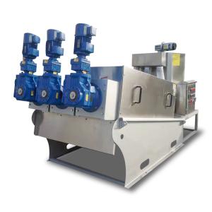
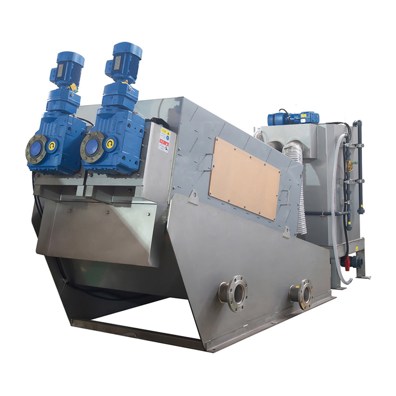
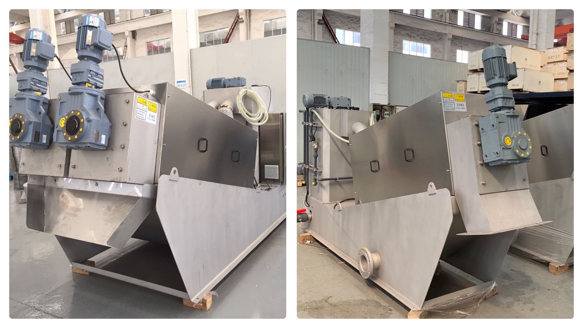
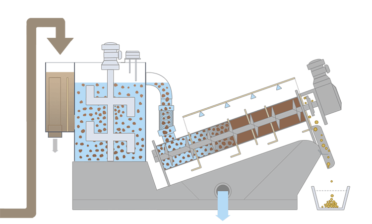
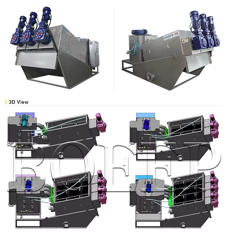
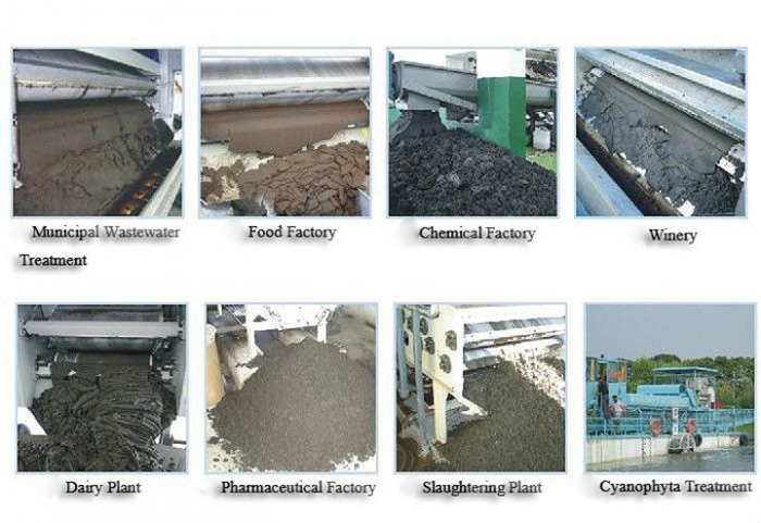
The screw sludge dewatering machine — also known as multi-disc screw press or spiral sludge dehydrator — is widely used in municipal wastewater treatment plants, food processing facilities, chemical plants, livestock farms, and textile mills. Unlike traditional Belt filter presses or plate-and-frame presses, the screw dewatering machine uses a stacked ring design with low-speed rotation (typically 2–6 rpm), delivering energy-efficient, continuous, fully automatic operation.However, prolonged continuous operation, fluctuating sludge characteristics, improper chemical dosing, and neglected daily maintenance can lead to frequent mechanical, electrical, and process failures. If left unresolved, these issues reduce dewatering efficiency, increase suspended solids in the filtrate, cause unplanned shutdowns, and drive up spare parts costs.
This article systematically covers the 8 most common faults in screw sludge dewatering machines — analyzing root causes, providing standardized repair procedures, and establishing a complete preventive maintenance system based on operational data from over 120 wastewater treatment facilities.
1. Core Technical Specifications
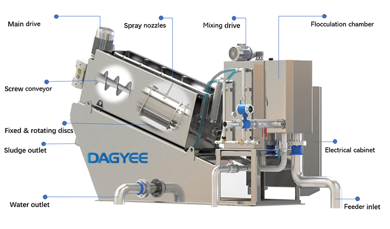
The table below lists standard parameters for mainstream industrial and municipal models, covering common 304 stainless steel screw dewatering machines. These specifications match most on-site equipment and serve as a useful reference during fault diagnosis and parameter tuning.
DL Series — Technical Specifications
Screw sludge dewatering machine — standard model parameters for reference
| Model | DS Capacity (kg/h) | Spiral Diameter (mm) | Discharge Distance (mm) | Dimensions (mm) | Net Weight (kg) | Running Weight (kg) | Power (kW) | Wash Water (L/h) | |||
|---|---|---|---|---|---|---|---|---|---|---|---|
| Min | Max | L | W | H | |||||||
| DL202 | 18 | 30 | 200×2 | 350 | 2500 | 935 | 1270 | 470 | 730 | 1.11 | 64 |
| DL301 | 30 | 50 | 310×1 | 495 | 3255 | 985 | 1600 | 850 | 1320 | 0.74 | 40 |
| DL302 | 60 | 100 | 310×2 | 495 | 3455 | 1295 | 1600 | 1200 | 2230 | 1.11 | 80 |
| DL303 | 90 | 150 | 310×3 | 495 | 3605 | 1690 | 1600 | 1520 | 3080 | 1.86 | 120 |
| DL352 | 120 | 200 | 350×2 | 580 | 4240 | 1550 | 2190 | 1950 | 3400 | 3.75 | 144 |
| DL353 | 180 | 300 | 350×3 | 580 | 4460 | 2100 | 2190 | 2600 | 4850 | 6 | 216 |
| DL402 | 120 | 200 | 410×2 | 585 | 4140 | 1550 | 2250 | 2450 | 3400 | 3.75 | 144 |
| DL403 | 180 | 300 | 410×3 | 585 | 4420 | 2100 | 2250 | 3350 | 4850 | 6 | 216 |
Note: DS = Dry Solids. Specifications are for reference only — consult factory drawings for final dimensions. For custom models or special material requirements (316L stainless steel, higher capacity), contact DAGYEE sales team for a tailored quote.
Fault 1: Screw Shaft Seizure and Complete Jamming (Most Frequent Failure)
Symptoms:
• Drive motor triggers overload protection; VFD displays over-current alarm
• Screw shaft cannot be turned manually after power-off; hardened sludge buildup visible inside the stack
• No sludge cake discharge; filtrate flow drops sharply
Root Causes:
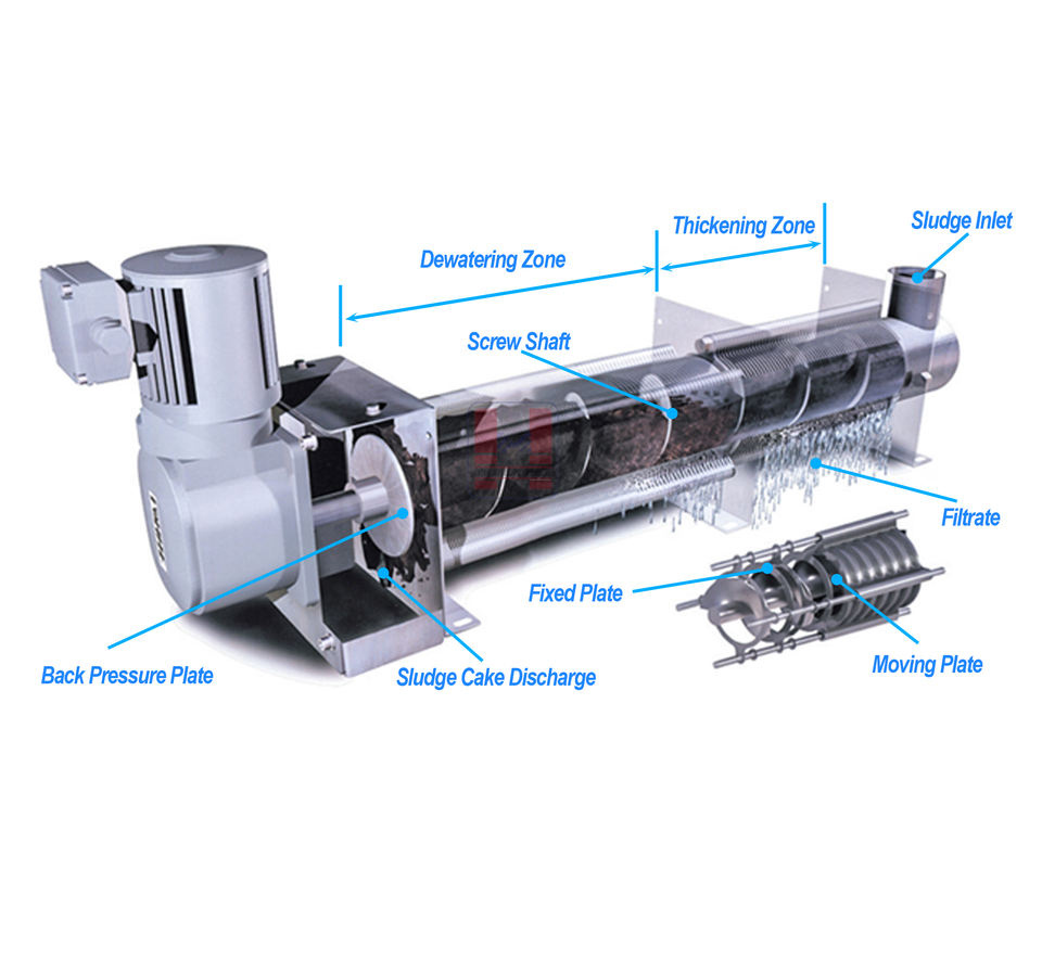
• Abnormal sludge characteristics — high sand, fiber, grease, or sticky organic colloids; untreated coarse debris wraps around screw flights
• Poor flocculation — mismatched PAM grade, insufficient dissolution, or under-dosing leads to loose flocs that stick to rings and shaft
• Improper operation — feeding beyond rated capacity; no pre-rinse before start; no empty-run cleaning after shutdown, leaving sludge to harden inside
• Manufacturing defects — poor dynamic/static ring flatness; uneven assembly gaps; rough screw surface promotes adhesion
Repair Procedures:
• Mild blockage: Stop feed pump; activate automatic backwash spray; run screw in reverse for 3–5 minutes to loosen deposits; then run forward empty for 20 minutes.
• Moderate blockage: Lock out power; remove side covers; flush sludge stack with high-pressure water from both ends; scrape solidified mud with plastic scraper to avoid scratching stainless steel surfaces.
• Severe jamming: Fully disassemble the ring stack; withdraw screw shaft; soak rings and flights in alkaline cleaning solution for 2 hours; polish scratches with fine abrasive cloth; reassemble after complete drying.
Prevention:
• Install a pre-screen basket and magnetic separator at the sludge inlet
• Test PAM flocculation daily to ensure floc size exceeds 5mm
• Follow SOP: 10-second spray before start; 30-minute empty running after feed stops
Symptoms:
• Motor surface temperature exceeds 85°C during operation; burning smell from reducer
• Operating current 1.5–2 times higher than rated; thermal relay trips frequently
• Screw speed drops; sludge cake output decreases by more than 40%
Root Causes:
• High process resistance: Partial blockage in the stack, excessive back pressure, or poorly flocculated sludge increasing screw torque
• Increased mechanical friction: Worn bearings, loose ring stack bolts, deformed rings creating metal-on-metal contact
• Electrical issues: Unbalanced three-phase power, aging motor insulation, deteriorated gearbox oil increasing transmission resistance
Troubleshooting Steps:
• Check parameters first — record feed rate, PAM dosage, back pressure gap; reduce feed volume by 30%; adjust back pressure to lower extrusion resistance
• Inspect mechanical friction — power off; manually rotate shaft to feel resistance; disassemble bearing housing; replace grease or damaged bearings; evenly retighten stack bolts
• Check electrical system — measure three-phase voltage balance; check motor winding insulation; drain old gear oil; refill with food-grade stainless steel compatible lubricant
Maintenance Standard:
• Replace reducer oil every 2,000 operating hours
• Replenish bearing grease every 7 days of continuous operation
Fault 3: Abnormal Vibration and Metallic Friction Noise
Symptoms:
• Violent machine shaking during operation; metal scraping or knocking sounds from the ring stack
• Vibration amplitude exceeds 0.12mm; foundation bolts loosen within 1–2 weeks
• Localized wear marks on dynamic and static rings after disassembly
Root Causes:
• Screw shaft eccentricity: Overload-induced bending, uneven flight wear, or misalignment after reassembly
• Foreign metal particles trapped between rings: Scrap iron, stones, or wire fragments scratching ring surfaces
• Foundation issues: Uneven base, loose anchor bolts, aging rubber shock absorbers
Repair Workflow:
• Immediately cut power to prevent further ring damage; disassemble ring stack; remove all foreign objects
• Check shaft concentricity with a dial gauge; straighten minor bends with mechanical press; replace severely deformed flights
• Level the machine base with steel shims; torque all anchor bolts; replace cracked or aged rubber pads
Fault 4: Sludge Leakage into Filtrate and High Suspended Solids in Effluent
Symptoms:
• Fine sludge particles escaping through ring gaps; filtrate SS exceeding 150 mg/L
• Sludge splashing from the side of the ring stack during high-load operation
Root Causes:
• Ring wear: Long-term friction enlarges ring gaps beyond 1.2mm (standard gap: 0.5–1.0mm)
• Poor flocculation: Small, loose flocs fail to retain solids; fine particles penetrate the gaps
• Uneven ring stack assembly: Uneven bolt compression creates localized gap enlargement
Repair Solutions:
• Optimize PAM dosage and dissolution concentration; run daily jar tests to ensure stable floc formation
• Replace worn moving rings with new 304 stainless steel or ceramic wear-resistant rings; reassemble with uniform bolt pressure
• Adjust gasket thickness between ring groups to maintain gaps at 0.6–0.9mm
Fault 5: High Moisture Content in Sludge Cake (Poor Dewatering)
Symptoms:
• Discharged cake is soft and sticky; moisture content exceeds 85% (design target: 75–80%)
• Low solids recovery; larger cake volume increases hauling costs
Root Causes:
• Back pressure plate gap too wide: Reduces internal extrusion pressure
• Feed sludge concentration too low: Excess free water enters the machine
• Screw speed too high: Short sludge residence time; incomplete water separation
• Severe ring wear: Reduces interlayer compression force
Operational Adjustments:
• Reduce screw speed to 2–4 rpm via VFD; narrow back pressure gap based on sludge organic content
• Install a sludge thickener upstream to raise feed solids to 3–5%
• Replace aged moving rings to restore original extrusion pressure
Fault 6: Distortion and Deformation of Dynamic and Static Rings
Symptoms:
• Ring plates warped or bent; uneven wear patterns; frequent sludge leakage and blockage shortly after repair
Root Causes:
• Overload operation: Prolonged high extrusion pressure deforms the ring structure
• Hard impurities in sludge: Sand and grit create point-load pressure on ring surfaces
• Poor material quality: Thin ring plates with insufficient yield strength
Maintenance Standard:
• Mild deformation: Flatten using a stainless steel leveling fixture; reinstall after flatness inspection
• Severe bending or cracking: Replace with thickened wear-resistant stainless steel rings; reinforce pre-screening to reduce hard particles
Fault 7: Water and Lubricant Leakage at Shaft End Bearings
Symptoms:
• Water seeps into bearing housing; grease emulsifies; oil drips onto sludge cake, causing contamination
Root Causes:
• Aging shaft-end skeleton oil seals; wear from long-term sludge water exposure; insufficient seal gland compression
Repair Process:
• Remove bearing end cover; extract worn oil seals and water retaining rings
• Install new fluorine rubber seals; evenly tighten gland bolts; refill with water-resistant lithium grease
Symptoms:
• Machine fails to start; touchscreen displays sensor alarm; torque limiter trips without mechanical blockage
Root Causes:
• Clogged liquid level sensor probes; loose torque limiter wiring; aging thermal switches; cable short circuits in humid environments
Electrical Maintenance Steps:
• Clean sludge deposits from all sensors; re-secure loose signal terminals
• Replace aging thermal relays and damaged torque limiters; seal exposed cables with waterproof tape
• Drain condensation from control cabinet; install a dehumidifier to reduce short-circuit risk
3. Quick Fault Self-Diagnosis Guide (5-Minute On-Site Check)
Quick Fault Self-Diagnosis Guide
5-minute on-site check — identify the problem fast
| Symptom | Priority Fault | First Action | Time |
|---|---|---|---|
| Over-current alarm + sudden shutdown | Stack blockage / bearing seizure | Stop feed; run reverse idle | 1 min |
| Cake moisture suddenly high, no alarm | Back pressure too wide / low feed solids | Adjust back pressure plate | 2 min |
| Metal scraping noise + machine shaking | Foreign objects between rings / shaft eccentricity | Emergency stop; check ring gaps | 1.5 min |
| Fine sludge overflow in filtrate | Ring wear / excessive assembly gap | Adjust PAM dosage temporarily | 2 min |
| Motor overheating + burning smell | Old reducer oil / unbalanced voltage | Stop; cool down motor | 3 min |
| Sensor alarm; machine won't start | Clogged sensor / loose wiring | Clean sensor surface | 1 min |
How to use: This guide helps field operators diagnose issues quickly without specialized tools, cutting fault identification time by up to 80%. Suitable for frontline wastewater plant daily operations.
This guide allows operators to diagnose issues quickly without specialized tools, cutting fault identification time by 80%.
For a full overhaul every 12 months, follow these standardized steps to avoid secondary damage:
1. Pre-overhaul preparation: Stop feed; run empty cleaning for 30 minutes; disconnect power; apply lockout/tagout.
2. Remove side baffles; disassemble back pressure plate and discharge hopper.
3. Loosen all stack compression bolts progressively; remove dynamic and static rings one by one for inspection and cleaning.
4. Extract screw shaft using a hoist; inspect flight wear, shaft concentricity, and bearing condition.
5. Clean all components with alkaline detergent; polish scratched surfaces; replace all severely worn parts.
6. Reassemble rings in original order; tighten bolts evenly with a torque wrench to ensure consistent gaps.
7. Reinstall shaft and bearings; refill lubricant; reset back pressure clearance based on sludge parameters.
8. Reconnect control circuits and spray lines; conduct a 1-hour no-load test to check vibration, noise, and current stability.
9. Run a load test with actual sludge; adjust PAM dosage and back pressure until cake moisture meets specifications.
Daily (Before and After Each Shift):
• Check motor current, surface temperature, and vibration/noise levels
• Run automatic backwash after shift to clean sludge stack
• Inspect filtrate clarity; adjust PAM dosage if flocculation is poor
• Remove debris from the inlet pre-screen basket
Weekly:
• Replenish lithium grease on shaft end bearings
• Check anchor bolt tightness and shock absorber condition
• Clean electrical cabinet; test sensor sensitivity
Monthly:
• Check reducer gear oil quality; replace if emulsified
• Measure dynamic/static ring gaps; record wear data for future planning
• Calibrate back pressure plate opening and VFD speed parameters
Annual:
• Full disassembly; inspect all components; replace all wear parts; calibrate shaft concentricity; upgrade electrical components; full performance test
Vulnerable Parts Replacement Cycle & Maintenance Cost Comparison
Core wearing parts — service life, cost, and maintenance tips
| Component | Service Life | Replacement Cost | Replacement Difficulty | Life Extension Tip |
|---|---|---|---|---|
| Dynamic & Static Rings | 8,000–10,000 hrs | Medium | Medium | Daily backwash; reduce grit intake |
| Shaft End Seals | 2,500–3,000 hrs | Low | Easy | Use fluorine rubber seals |
| Screw Shaft Bearings | 5,000–6,000 hrs | Medium | Medium | Grease every 7 days |
| Reducer Oil | 2,000 hrs | Low | Easy | Change on schedule to avoid gear wear |
| Torque Limiter & Sensors | 12–18 months | High | Hard | Dehumidify control cabinet regularly |
| Base Rubber Pads | 10–12 months | Very low | Easy | Avoid prolonged vibration from overloading |
Best Practice: Record ring wear thickness monthly and stock spare rings in advance to avoid unplanned shutdown. Removing sand, fiber, and hard particles upstream can reduce screw and ring wear by over 50%.
• Record ring wear thickness monthly; stock spare rings in advance
• Remove sand, fiber, and hard particles upstream — this alone can reduce screw and ring wear by over 50%
• Provide regular SOP training; poor manual adjustments account for roughly 60% of sudden equipment failures
• Choose corrosion-resistant 304/316L stainless steel consumables to extend service life and reduce long-term costs
Most screw sludge dewatering machine failures come down to three root causes: improper operation and chemical conditioning; mechanical wear without scheduled maintenance; and raw sludge quality fluctuations. By accurately diagnosing symptoms, following standardized repair procedures, and implementing a structured preventive maintenance system, you can effectively eliminate over 90% of common breakdowns.
For complex mechanical deformations or deep electrical control issues, always involve qualified environmental equipment technicians to avoid irreversible damage to the core screw shaft and ring stack.