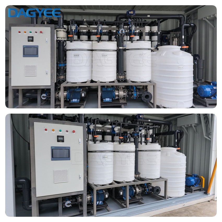
UF Membrane Autopsy & Failure Analysis Service – Root Cause Diagnostics for Membrane Performance Issues
In recent years, surface water purification with ultrafiltration membrane has become an attractive alternative to conventional clarification. No or less need of chemical agents, good quality of produced water independent of feed water quality, good removal efficiency towards microorganisms, less production of sludge, compact process, and easy automation are some of the advantages of ultrafiltration compared to conventional treatment. Originally, ultrafiltration was used to remove turbidity and microorganism from good-quality surface water. Nowadays the main goal is to improve this technology and to apply it to worse quality sources for the removal of microorganisms, natural organic matter (NOM), Total Organic Carbon (TOC) including particulate organic carbon (POC) and dissolved organic carbon (DOC), disinfection by-products (DBPs) and other components.
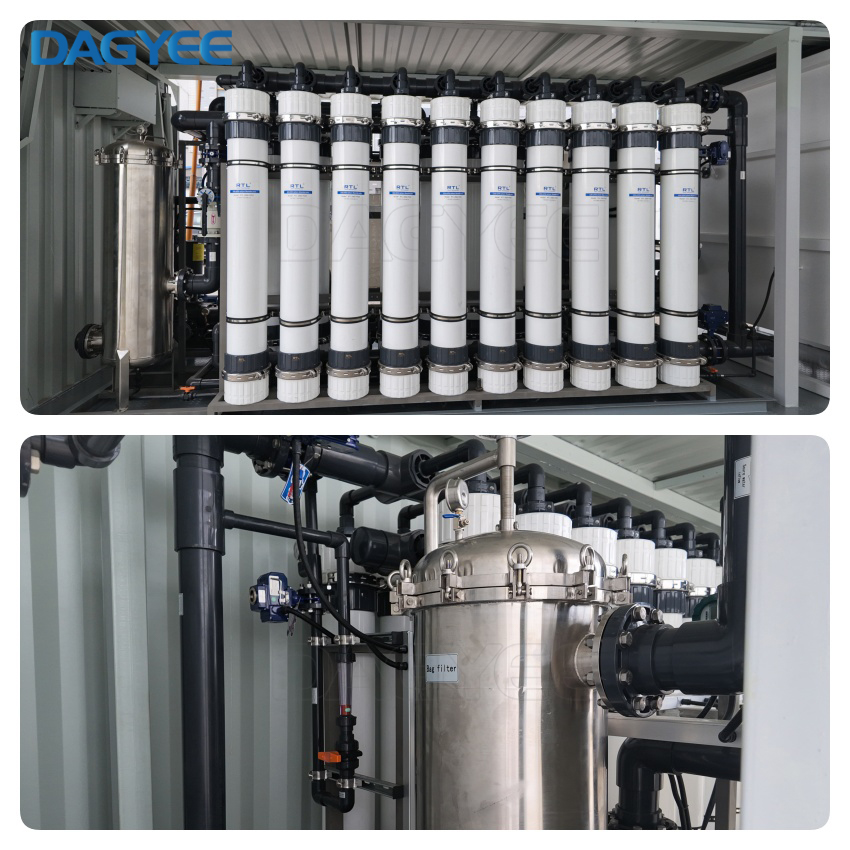
Product Overview
Your UF membrane system is performing poorly. The flux is dropping. The pressure is rising. The permeate quality is declining. You've tried cleaning. You've adjusted operating conditions. Nothing works. And you're about to spend $50,000 or more on new membranes.
But what if you knew exactly what was causing the problem? What if you understood why the membranes are failing? And what if you had a clear roadmap to prevent it from happening again?
The DAGYEE UF Membrane Autopsy & Failure Analysis Service provides the answers. We take a representative membrane sample from your system, analyze it in a fully equipped laboratory, and identify the root causes of fouling, degradation, and failure. The result is a detailed report that explains:
What is fouling your membranes
Why it's happening
How to fix it
How to prevent it from happening again
This service pays for itself the first time it saves you from an unnecessary membrane replacement or helps you optimize your cleaning program.
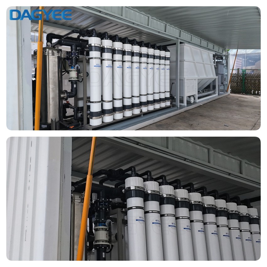
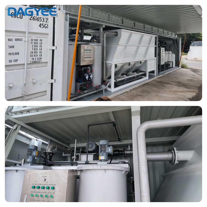
Why a Containerized System?
There are plenty of reasons to put a water treatment plant inside a shipping container. Here are the ones that matter most:
Speed of Deployment
A conventional water treatment plant takes months to design, build, and commission. A containerized system takes days to ship and hours to commission. When water is urgently needed, that difference is everything.
Complete Mobility
The system is built to move. A flatbed truck delivers it. A crane sets it down. When the project ends, the same truck takes it to the next site. The equipment doesn't get left behind—it follows the work.
Minimal Civil Works
No foundations. No buildings. No permanent utilities. Just a reasonably level piece of ground, a water source, and a power connection. That's all it takes.
Plug-and-Play Simplicity
Everything is pre-installed and pre-wired inside the container. The operator doesn't need to be a water treatment specialist. The system is designed to be operated by someone with basic training. Connect the hoses, turn it on, and let it run.
Weather Protection
The container provides built-in shelter for all equipment. Rain, dust, wind, and extreme temperatures don't affect performance. The system operates reliably in conditions that would shut down an open-air plant.
Security
The container is lockable, providing physical security for equipment in remote or unstable locations. Vandalism and theft are real concerns in some settings—a shipping container offers practical protection.
Working Principle
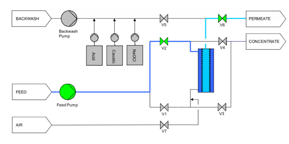
The system uses two standard methods for integrity testing:
Option A: Pressure Decay Test (PDT)
This is the most common and quickest test method.
Step 1: Isolate the Module
The membrane module is isolated from the rest of the system. Feed and permeate valves are closed.
Step 2: Apply Pressure
The tester applies compressed air at controlled pressure to the feed side of the membrane. The permeate side is open to atmosphere.
Step 3: Measure Pressure Decay
The pressure is held for a set period (typically 5-20 minutes). The tester measures the rate of pressure decay. Intact membranes will hold pressure. Damaged membranes will show a pressure drop.
Step 4: Pass/Fail Result
If the pressure decay exceeds a preset threshold, the test fails. The tester automatically calculates the result.
Option B: Bubble Point Test
This method is more sensitive but requires a clean membrane.
Step 1: Wet the Membrane
The membrane is wet with clean water to fill all pores.
Step 2: Apply Air Pressure
Air pressure is slowly applied to the feed side while the permeate side is submerged in water.
Step 3: Observe Bubble Formation
When the pressure exceeds the bubble point pressure, air penetrates the largest pores and bubbles appear in the permeate. The bubble point pressure indicates the largest pore size present.
Step 4: Determine Integrity
If the bubble point pressure is below specification, the membrane has broken fibers or compromised pores.
System Components
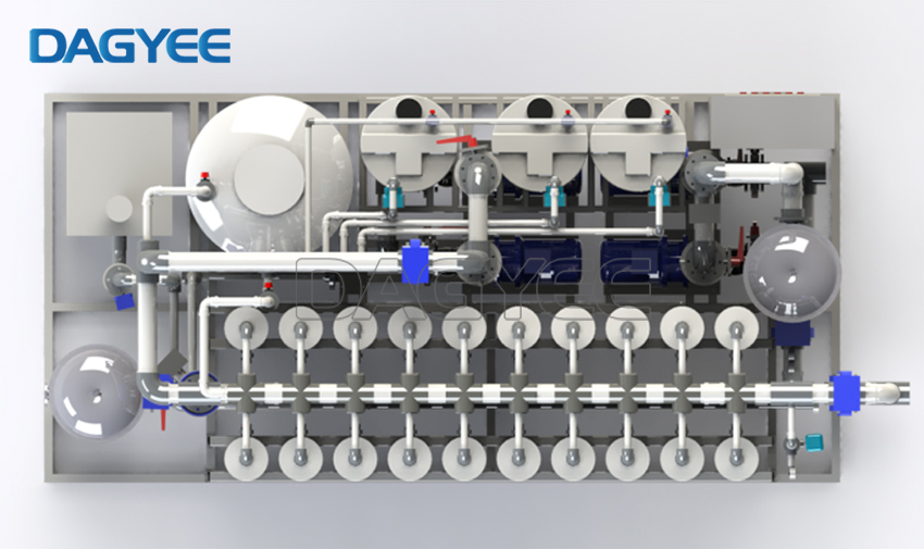
| Component | Function Description |
|---|---|
|
Core
|
Core filtration units; typically made of PVDF (Polyvinylidene Fluoride) or PES (Polyethersulfone), featuring excellent anti-fouling properties, high chemical resistance, and long service life. Available in inside-out or outside-in configurations. |
|
Feed Pump
Power
|
Provides stable operating pressure for the filtration process, typically ranging from 0.1 to 0.3 MPa. Designed for continuous duty with energy-efficient performance and low noise operation. |
|
Backwash System
Cleaning
|
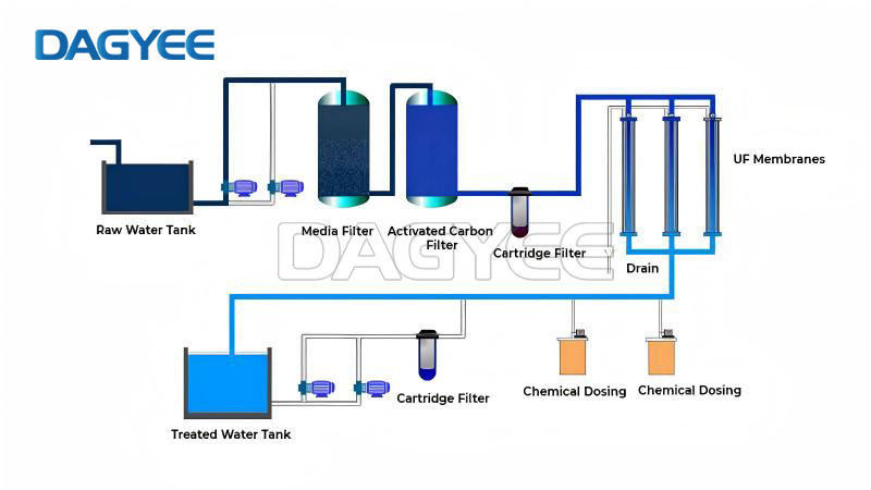
Periodically flushes the membrane with clean water or an air-water combination in the reverse direction to effectively remove surface fouling, restore membrane flux, and extend membrane lifespan. |
|
Chemical Cleaning System
CIP/CEB
|
Utilizes chemical agents such as NaClO (sodium hypochlorite), citric acid, NaOH, and EDTA for online (CEB) or offline (CIP) chemical cleaning to remove irreversible fouling and fully recover membrane performance. |
|
PLC Control System
Automation
|
Equipped with advanced PLC and HMI touch screen interface, enabling fully automated operation including automatic filtration, backwashing, chemical cleaning, TMP monitoring, alarm diagnostics, and optional remote control. |
|
Pre-filtration System
Protection
|
Includes disc filters or cartridge filters with 100~200 μm filtration precision to remove large suspended particles and protect the UF membranes from mechanical damage and premature clogging. |
|
Air Scouring System
Enhanced
|
Generates air bubbles during backwashing to enhance cleaning efficiency by creating turbulence and mechanical scouring on the membrane surface, significantly improving foulant removal. |
|
Tank & Piping System
Infrastructure
|
Comprises feed tank, permeate tank, backwash tank, and chemical dosing tanks, all constructed from high-quality corrosion-resistant materials such as UPVC or Stainless Steel 304/316L, ensuring durability and hygienic operation. |
What This System Removes
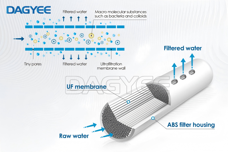
The Compact UF System is a physical barrier. It removes anything larger than its pore size. Here's what that means in practical terms:
| Contaminant | Removal Efficiency | Notes |
|---|---|---|
| Suspended solids | > 99.9% | Sand, silt, clay, and other particulate matter |
| Colloids | > 99.9% | Clay particles, silica, iron oxides |
| Bacteria | > 99.99% | Including E. coli, coliforms, and pathogenic bacteria |
| Viruses | > 99.99% | Including enteric viruses and rotaviruses |
| Protozoa | > 99.99% | Giardia, Cryptosporidium |
| Turbidity | To < 0.1 NTU | Consistently low, regardless of feed turbidity |
| Algae | > 99.9% | Removes algae cells and algal debris |
Ultrafiltration offers numerous advantages in water treatment, making it an increasingly popular choice for municipal and industrial applications. Hollow fiber UF membranes provide a physical barrier to suspended solids and pathogens to consistently produce a high-quality, low-turbidity, and low-SDI effluent.
Here are the key benefits of implementing an ultrafiltration system:
Pressurized or immersed membranes to suit the site requirements.
Greater output in the same footprint and helps reduce capital and lifecycle costs for the application.
Physical UF barrier provides consistent high-quality effluent exceeding stringent regulatory requirements through virtually any change in raw-water quality.
Low lifecycle cost optimized through extended membrane life and low energy and chemical use.
These benefits make ultrafiltration an attractive option for various water treatment applications, from municipal water supplies to industrial process water.
Technical Specifications
| Parameter | Specification |
|---|---|
| Filtration Precision | 0.01 ~ 0.02 μm |
| Membrane Material | PVDF (Polyvinylidene Fluoride) / PES (Polyethersulfone) |
| Membrane Configuration | Hollow Fiber (HFF) |
| Fiber Inner Diameter | 0.6 ~ 1.0 mm |
| Fiber Outer Diameter | 1.0 ~ 1.6 mm |
| Operation Mode | Inside-out / Outside-in |
| Operating Pressure | 1.4 ~ 3.5 bar (20 ~ 50 psi) |
| Maximum Operating Pressure | 6.0 bar (87 psi) |
| Operating Temperature | 2 ~ 38℃ (35 ~ 100℉) |
| Maximum Temperature | 45℃ (113℉) |
| Operating pH Range | 2 ~ 13 |
| pH Range (Cleaning) | 1 ~ 14 CIP |
| Recovery Rate | 85% ~ 95% |
| Permeate Turbidity | < 0.1 NTU |
| Permeate SDI | < 1 RO Feed |
| Bacteria Removal Rate | > 99.99% |
| Virus Removal Rate | > 99.99% |
| Chlorine Tolerance (PVDF) | > 2,000 ppm Continuous |
| Power Supply | 220V / 380V ± 10%, 50/60Hz, 3 Phase |
| Control System | PLC + HMI Touch Screen Fully Automatic |
| Protection Class | IP54 (Standard) / IP65 Optional |
What Does Ultrafiltration Remove?
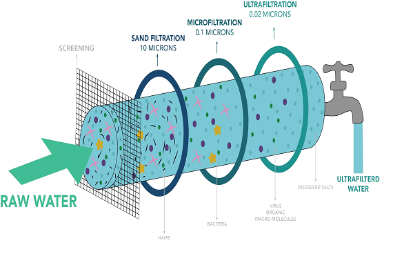
Ultrafiltration is highly effective at removing a wide range of contaminants from water. Here's a breakdown of what an ultrafiltration water filter can typically remove:
1. Particulate matter:
Suspended solids
Colloids
Turbidity
2. Microorganisms:
Bacteria (99.99% removal)
Protozoa (including Giardia and Cryptosporidium)
Many viruses
3. Organic compounds:
High molecular weight organics
Some humic substances
4. Inorganic compounds:
Some heavy metals, when bound to organic matter or particles
5. Other contaminants:
Algae
Some parasites
It's important to note that while ultrafiltration is highly effective at removing many contaminants, it does not remove contaminants like dissolved salts, organic molecules, or ions smaller than the pore size. Additional treatment methods like reverse osmosis or ion exchange may be necessary for these.
Installation & Setup
One of the advantages of the Compact UF System is its simplicity. Here's what you need to know:
What You Get
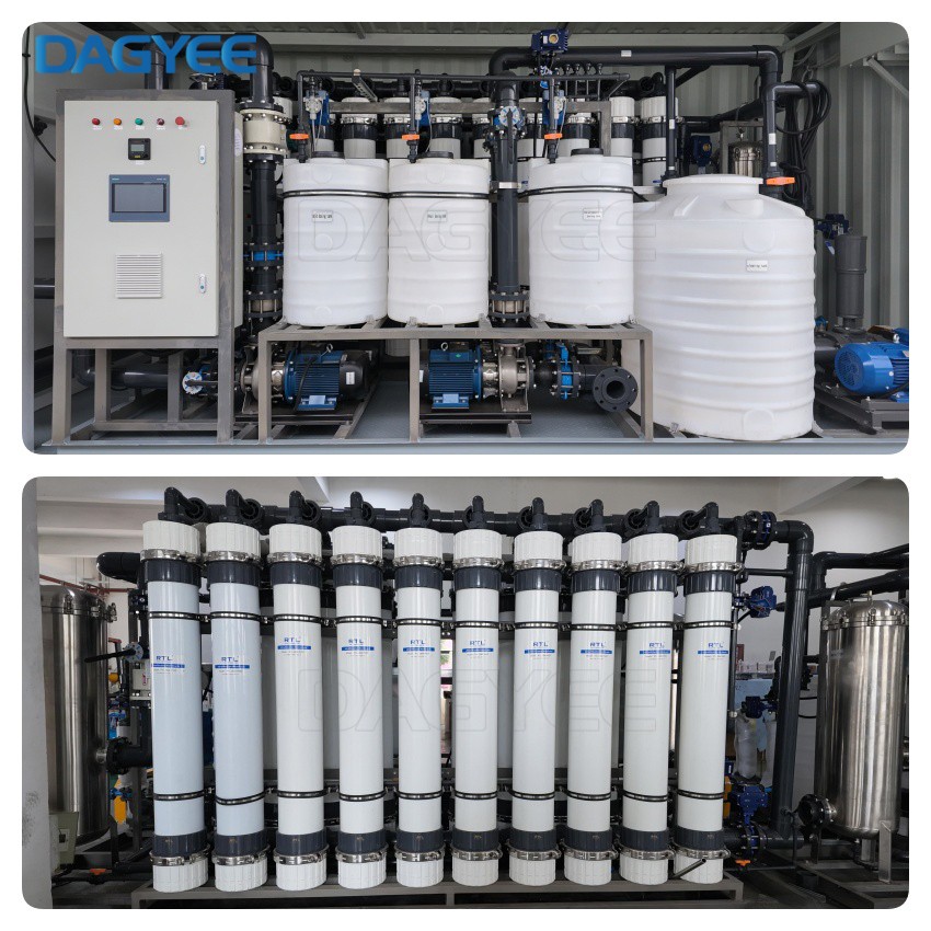
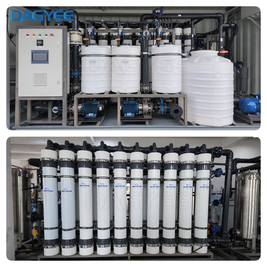
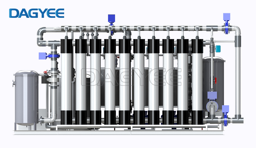
The system arrives fully assembled on a steel skid. All piping, the UF membrane modules, the feed pump, the control panel, and the instrumentation are already connected. The pre-filter is installed. The backwash system is plumbed. It's essentially plug-and-play.
Connection Requirements
Water Supply: Pipe connection to your feed water source (well, tank, municipal supply, or surface water)
Permeate Discharge: Pipe connection to your product water tank or distribution system
Reject / Drain Discharge: Pipe connection to drain or recycle line (small flow, typically 5-10% of feed)
Power: Single-phase electrical connection at the specified voltage
Space: Level